


A choke and kill manifold is a packaged pressure-control system that lets a drilling crew circulate a kick, hold back pressure on the well, and route fluids to safety without exposing the rig to uncontrolled flow. It combines valves, adjustable and positive chokes, gauges, pipework, and a skid in one assembly, and it is normally connected to the blowout preventer stack through the choke and kill lines.
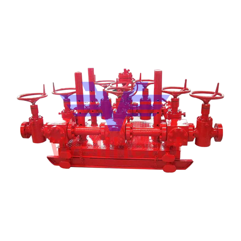 API 16C Choke Manifold for Well Pressure ControlPackaged choke-and-kill manifold with valves, chokes, gauges, and skid for controlled kick circulation and pressure holding.View Product →
The practical value is simple: during a kick, the manifold gives the crew a controlled path to circulate heavier mud while the choke holds casing pressure within limits. If the manifold is undersized, poorly laid out, or fitted with the wrong trim, that control window narrows quickly.
What the Manifold Does During a Kick
The choke and kill manifold’s core job is to turn a dangerous well-control event into a controlled circulation problem. The kill line gives the crew a route to pump heavier mud into the well; the choke line gives a route to take returns from the well; and the choke side lets the operator hold back pressure while the mud weight is increased.
In a typical kick response, the crew closes the blowout preventer, lines up the choke manifold, and uses an adjustable choke to maintain casing pressure while bringing the kill mud up to weight. The manifold must handle abrasive solids, rapid pressure changes, and repeated make-up and break-out of lines. That is why valve arrangement, choke trim, and pressure rating matter as much as the headline pressure class.
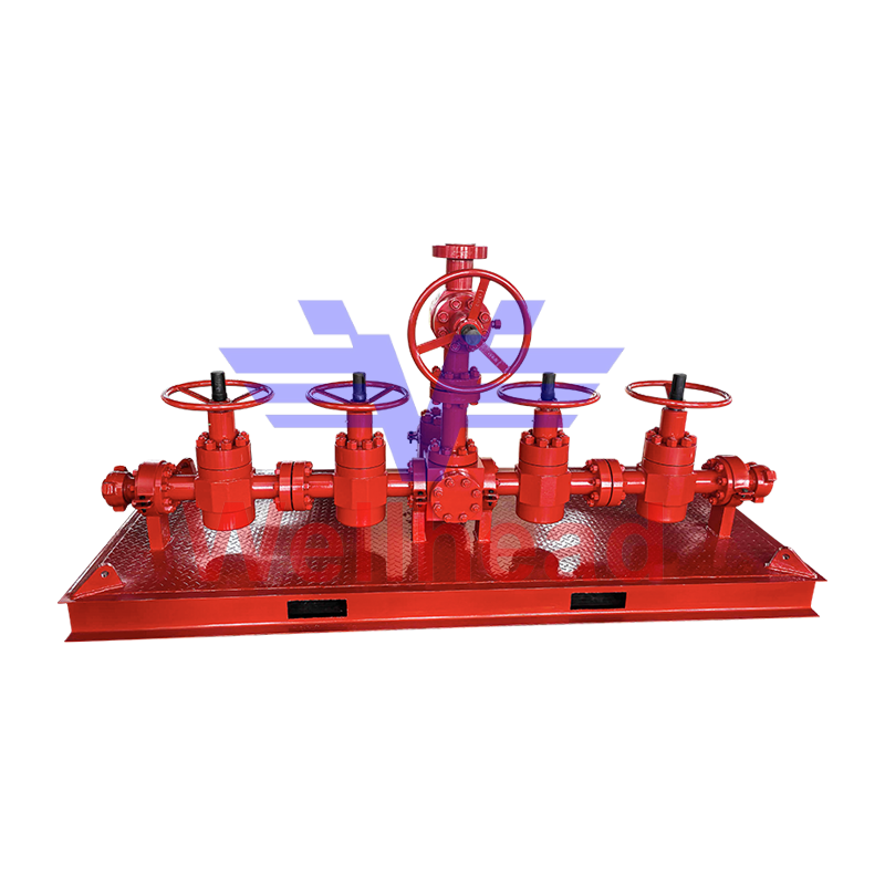 API 16C Kill Manifold for Well-Control CirculationClosed circulation manifold that routes heavy mud to the wellhead to manage wellbore pressure during kicks and pressure-control operations.View Product →
A useful way to judge a manifold layout is to ask whether one operator can see the pressure gauges, reach the choke control, and confirm valve positions without crossing the flow path. In tight rig spaces, that ergonomic detail often decides whether pressure control stays smooth or becomes reactive.
Components and Flow Path
A choke and kill manifold is built around a clear split between the choke side, the kill side, and the shared skid that ties them together. The choke side usually includes an adjustable choke, a positive choke, upstream and downstream plug or gate valves, pressure gauges, and a buffer or relief path where specified; the kill side includes isolation valves and a direct route to the wellbore.
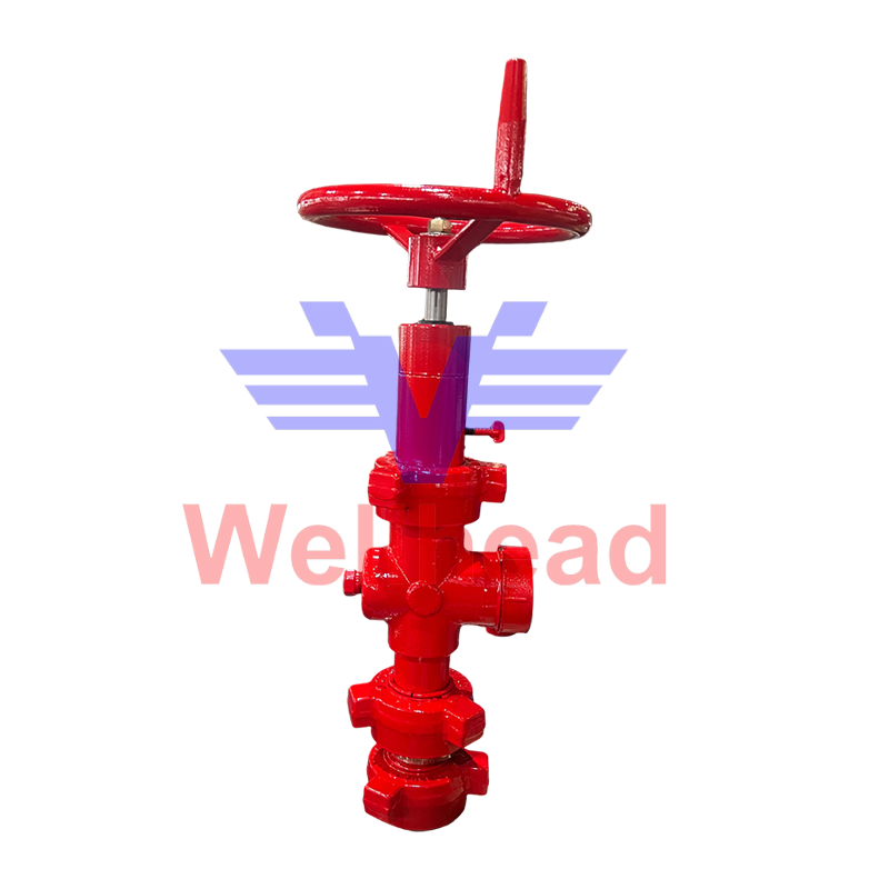 H2 Adjustable Choke Valve with Hammer Union ConnectionsAdjustable throttling choke for precise flow and pressure control in abrasive service, with maintenance-friendly design for repeated pressure-control adjustments.View Product →
Choke side
The choke side is the pressure-control side, so its first requirement is fine, repeatable adjustment rather than simple on-off isolation. Adjustable chokes let the operator make small changes as pump rate, mud weight, and gas cut change; positive chokes are fixed-orifice devices used when a known bean size is preferred. Trim wear is normal in abrasive service, so the choke should be easy to isolate, drain, and service.
Kill side
The kill side is the injection side, and its main risk is a lineup error rather than fine control. It needs clear labeling, reliable isolation, and a flow path that matches the rig’s kill line and pumping plan. Cross-connections can be useful, but they also increase the number of valve positions that must be verified before pumping starts.
Shared skid, gauges, and piping
The skid and piping tie the two sides into one testable package. Poorly placed gauges, blocked impulse lines, or piping that traps sand can make a good valve package behave badly. The manifold should drain fully, avoid unnecessary low pockets, and leave enough room for torque tools and flange alignment during maintenance.
API 16C Ratings, Sizing, and Selection Criteria
The main selection decision is not simply “the highest pressure class wins”; it is matching API 16C rating, bore, trim material, valve arrangement, and test evidence to the actual well program. A 15,000 psi manifold with the wrong trim or a cramped layout can be less useful than a correctly specified lower-pressure package.
| Item | Choke side | Kill side |
|---|---|---|
| Primary role | Regulate outflow and hold backpressure | Provide a route to pump kill fluid |
| Typical control device | Adjustable choke or positive choke | Isolation valves and line-up valves |
| Normal operating focus | Smooth pressure changes and trim wear | Positive isolation and correct flow path |
| Common failure mode | Plugged or washed choke trim | Valve seat leak or wrong lineup |
For procurement, check the API 16C temperature class, pressure class, product specification level, and performance requirement against the drilling program. Confirm the bore and end connections match the rig’s choke and kill lines, then check valve types, choke trim material, gauge ranges, and lifting points. In abrasive or corrosive service, material certificates and trim selection deserve close review because a low-cost trim can disappear into maintenance cost within a few wells.
Testing is another selection criterion. Pressure tests, functional tests, and documentation should follow the applicable API 16C requirements, with hold periods and acceptance criteria recorded. Ask for the test chart, not just a pass certificate, and confirm that gauges have a current calibration record.
Procurement Checklist: What to Confirm Before Order
The safest purchase process is to confirm the operating envelope, then the physical interface, then the documentation package. That order prevents a late discovery that the manifold fits the pressure rating but not the rig floor.
- Define the maximum anticipated surface pressure, mud weight range, and kick circulation method.
- Confirm API 16C pressure class, temperature class, bore, and end connections.
- Select choke type and trim for expected sand content, fluid corrosivity, and adjustment frequency.
- Review valve arrangement, drain points, gauge placement, and lifting or stowing details.
- Require pressure test records, functional test records, material certificates, and calibration certificates.
- Agree on spare trim, seals, gauge protection, and service access before delivery.
For a faster technical review, start with the API 16C manifold series and compare the choke and kill configurations against the rig line-up. A good supplier should be able to explain why a particular valve arrangement, choke trim, and test sequence suits the well program, not just quote a pressure class.
Common Operating Problems and Test Checks
Most manifold problems show up as unstable pressure control, not as a sudden catastrophic failure. The usual causes are plugged chokes, washed trim, leaking valve seats, blocked gauge lines, and incorrect valve lineups after maintenance.
- Erratic casing pressure may come from a partially plugged choke or a gauge line filled with solids.
- A choke that needs constant adjustment may have worn trim, especially after abrasive returns.
- Pressure creep on a closed valve can indicate seat damage or debris on the sealing surface.
- Wrong lineup is more likely when valves lack clear tags or when cross-connections are undocumented.
- Late detection of leaks often traces back to missing calibration or poor gauge visibility.
Before each well, pressure-test the assembled manifold, function-test the chokes through their full range, confirm gauge calibration, and walk the line-up with the crew. After a kick or abrasive circulation, inspect choke trim and valve seats rather than waiting for the next pressure test to reveal wear.
FAQ
What is the difference between a choke manifold and a kill manifold?
The choke manifold controls outflow and backpressure through a choke, while the kill manifold provides a controlled route to pump kill fluid into the well. They are often supplied on one skid because they work together during well control.
What pressure class should I choose?
Choose the lowest API 16C pressure class that safely covers the maximum anticipated surface pressure with the required design margin and rig interface. Higher is not automatically better if the bore, trim, or layout does not match the operation.
How often should the manifold be tested?
Test before each well or according to the operator’s well-control program, and after maintenance or abnormal service. Pressure and functional tests should follow API 16C requirements and be documented.
Can the manifold be customized?
Yes, but customization should stay within a tested design envelope. Common changes include valve arrangement, choke type, gauge placement, skid dimensions, lifting points, and end connections.
 +86-0515-88429333


 আমাদের সাথে যোগাযোগ করুন
